SZR Self-starting production power reserve activation systems (Automatic Switch Transfer) by Elstar Electric using PLC drivers are designed to continually supply electric power to facilities in which power supply intermissions may last less than a hundred milliseconds or up less than a hundred seconds . Using PLC drivers in these systems is presently standard for large, well-known in the world, electrical switchboards manufacturers.
SZR systems manufactured by us are based on specialized PLC drivers and can be applied in power supply systems with 2 or more switches. Such systems can also be exposed to visualization. With the help of visualization program a driver informs about the existing positions of switches, where power is supplied, failures present, and recent switching. Information can be stored and at any time read by a stationary computer, operating panel or a remote modem connection, the entire functioning history of each switch in the system can be known. SZR systems using PLC drivers ensure correct switching, in the situation of master switches path failure, maneuver switches and turning on or off power generator in several types of automatic work.
The notion path failure includes :
- voltage loss
- Switch pull out (in case such switch is present)
- switch cut off due to an overload or short circuit
- manual switch off during automatic work
SZR system, while working in the automatic mode, has a a capacity to work with a known or hidden reserve. In the first case it is possible to program a priority of power supply from the network 1 or 2 in the situation when there are two ways to supply power coming from ZE network. Automat controlling having an option to use the priority network ensures power supply solely from this network or in the case of its lack from a power generator.
In the control system the following delays are set :
- a delay in time of turning on switches, measured from the starting time of one of the paths failure -this prevents (if it is selected), unnecessary switching of the system in a situation of momentary voltage losses, which last a shorter time then set delays time.
- a delay in time of turning on master switches after voltage restoring, time is measured from the moment of restoring -it is set by the operator by external time relays, and it can last less than a few dozen seconds, it is supposed to prevent unnecessary switching of the system until stable parameters of power supply are restored.
- a delay of turning on the failure switch and after the signal to turn on the power generator (set according to a program), it enables to perform several attempts to start up power generator in the case of difficulties with its start up.
The time is individually selected for a given type of power generator. A failure in the path of a given turn off switch causes that a driver will block the switch and then will change the system and this way will ensure continuity of power supply bypassing this switch. SZR system makes a blockade, which then disables a given switch from being turned on again in the automatic work mode.
State of a switch blockade occurs in a driver in the following cases:
- a short or overload in the path of a switch
- incorrect switching from auxiliary points of the switch or damage to wires connecting contact points with binary input of a driver.
A driver recognizes state of overload or short and does not allow for a new switching on "on a short" (overload) with a simultaneous setting of a blockade. Removing blocking of a switch is done by pressing a button "blockade removal".
| Typ SZR | Liczba wyłączników | Liczba zasilań | Opis |
| SZR 2TT | 2 | 2 feeds from transformers | Basic feeds + reserve feed |
| SZR 2TG | 2 | 2 feeds from transformer station + Generator | |
| SZR 3TT | 3 | 2 transformer feeds | Basic feeds + reserve feed + clutch |
| SZR 3TG | 3 | 2 feeds from transformer + Generator | |
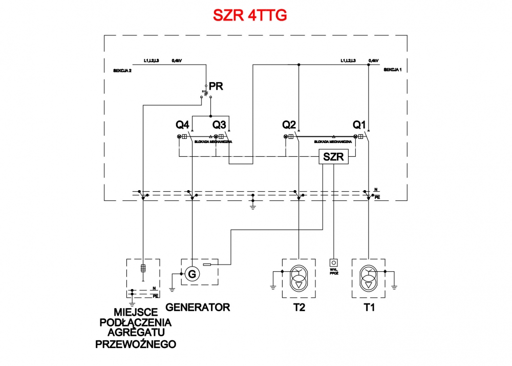
| SZR 4TTG | 4 | 2 feeds from transformer + Generator | Basic feeds + reserve feed |
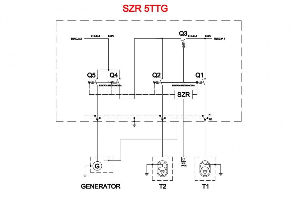
| SZR 5TTG | 5 | 3 feeds from transformer + Generator | |
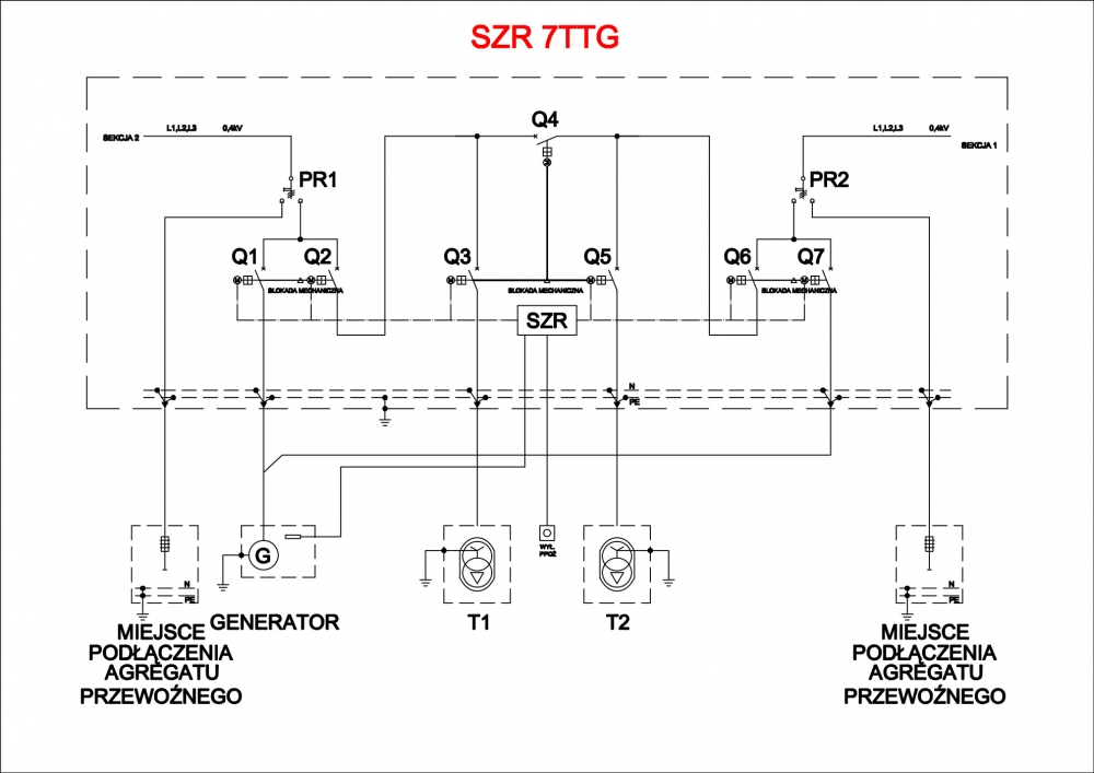
| SZR 7TTG | 7 | 3 feeds from transformer + Generator | |
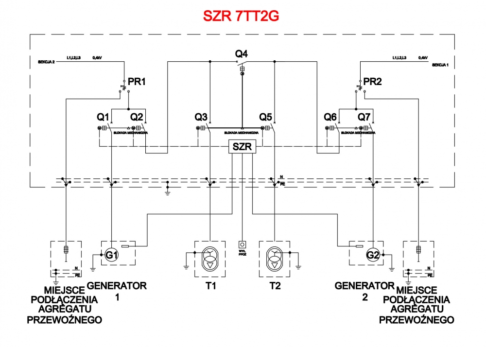
| SZR 7TT2G | 7 | 4 feeds - 2 from transformer and 2 Generators | |
| According to a project |
any configuration | any configuration | any configuration |
- there is a possibility of enlargement through system visualization.
- the lowest possible cost in relation to used appliances.
- fast project realization.
The system is based on PLC.
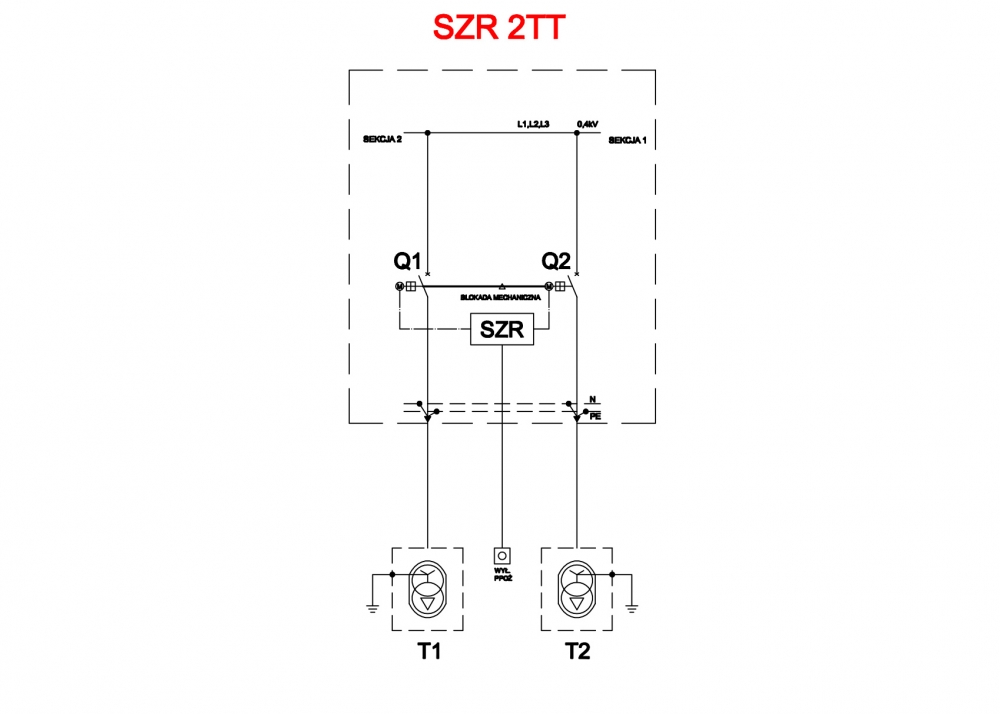
Controlling with two switches Q1 and Q2. The system has the primary power supply from T1 transformer and backup power supply from T2 transformer. You can adjust the switching times.
The exemplary system is as follows:
The system is based on PLC.
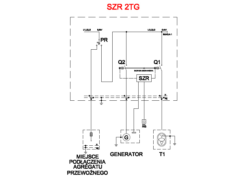
Controlling with two switches Q1 and Q2. The system has the primary power supply from T1 transformer and backup power supply from G generator. The system can be supplied from the transportable unit/aggregate. Start up of the system can be done with the controller or spontaneously. You can adjust the switching times.
The exemplary system is as follows:
The system is based on PLC.
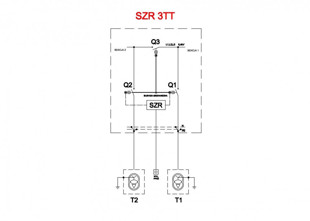
Controlling with the three switches Q1, Q2 and Q3. The system has the primary power supply from T1 transformer and backup power supply from T2 transformer. Such configuration allows for supplying the two sections from two different transformers, in case of power failure a clutch is switched on. You can adjust the switching times.
The exemplary system is as follows:
The system is based on PLC.
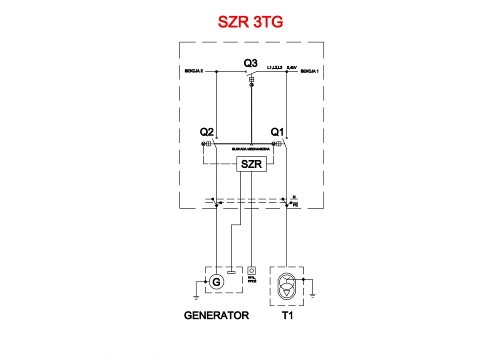
Controlling with the three switches: Q1, Q2 and Q3. The system has the primary power supply from T1 transformer and backup power supply from G generator. Such configuration allows for supplying the two sections from two different transformers, in case of power failure the clutch is switched on and it activates the backup power supply. The start up of the aggregate can be done by the controller or spontaneously. You can adjust the switching times.
The exemplary system is as follows:
The system is based on PLC.
Controlling with the four switches: Q1, Q2, Q3 and Q4. The system has the basic power supply of Sections I and II from T1 transformer T1 and backup power supply from T2 transformer. The system also has an additional/auxiliery power sources carried by two stationary and transportable generator. Such configuration allows for supplying two sections from two different transformers, what’s more, Section II has an additional power supply from two generators (fixed or transportable). The start up of the system can be done with the controller or spontaneously. You can adjust the switching times.
The exemplary system is as follows:
The system is based on PLC.
Controlling with five switches Q1, Q2, Q3, Q4 and Q5. The system has the basic power supply of Sections I and II from T1 transformer T1 and backup power supply from T2 transformer. In case of power failure a clutch is activated by Q3 switch. The system has also additional power supply from G generator. Such configuration allows for supplying two sections from two different transformers, in addition Section II has additional power supply from G generator. The start up of the system can be done by a controller or spontaneously. You can adjust the switching times.
An exemplary system is as follows:
The system is based on PLC.
Controlling with switches Q1, Q2, Q3, Q4, Q5, Q6 and Q7. The system has the basic power supply of Sections I and II from T1 transformer and backup power supply from T2 transformer. In case of power failure a clutch is activated by Q4 switch. The system also has additional power supply. Section II has an additional power supply from two generators (fixed or transportable). Section I has the additional power from transportable generator. The start up of the system can be done by a controller or spontaneously. You can adjust the switching times.
An exemplary system is as follows:
The system is based on PLC.
Controlling with seven switches Q1, Q2, Q3, Q4, Q5, Q6 and Q7. The system has the basic power supply of Sections I and II from T1 transformer T1 and backup power supply from T2 transformer. In case of power failure clutch is activated by Q4 switch. The system also has an additional power supply. Section II has an additional power supply from two generators (fixed or transportable). Section I has the additional power from transportable generator. The start up of the system can be done by a controller or spontaneously. You can adjust the switching times.
An exemplary system is as follows:
The system is designed on the basis of the device included in the project.
Switch control according to design logic formulated within the project.
For your convenience we provide you with offer inquiry module, which enables you to send us your project or express your ideas.
Contact us.

